
Byung Kyu Choi Riccardo Bettati
Department of Computer Science
Texas A&M University
College Station, TX 77843-3112, USA
{choib, bettati}@cs.tamu.edu
Tel:1-979-845-5469, Fax:1-979-847-8578
Abstract We propose a network-based endpoint admission control system for scalable QoS guaranteed real-time communication services. This system is based on a sink tree-based resource management strategy, and is particularly well suited for differentiated-services based architectures. By performing the admission decision at the endpoints, the flow setup latency and the signaling overhead are kept to a minimum. In addition, the proposed system integrates routing and resource reservation along the routes, and therefore displays higher admission probability and better link resource utilization. This approach achieves low overall admission control overhead because much of the delay computation is done during system configuration, and so resources can effectively be pre-allocated before run time. We investigate a number of resource sharing approaches that allow resources to be efficiently re-allocated at run time with minimized additional overhead. We provide simulation experiments that illustrate the benefits of using sink tree-based resource management for resource pre-allocation and for routing, both with and without resource sharing.
It is generally accepted that end-to-end
delay guarantees in networks and distributed systems
are provided by (i) appropriate allocation of resources
across the network, (ii) strict admission control, and (iii) traffic
monitoring and policing
in the network.
This rather straight-forward idea has been well studied,
organized in the form of the Integrated Services
architecture [3].
The most serious shortcoming for the Integrated Services architecture
is lack of scalability: All mechanisms within
the Integrated Services architecture rely on flow awareness.
Admission control, policing, and typically packet forwarding
all need to know per-flow information.
The most natural way to cope with this lack of scalability is to
aggregate flows into classes of flows, and then have the network
manage flow classes instead of individual flows.
This general approach is
followed in the IETF Differentiated Services architecture
[7,,].
The lack of per-flow information can negatively affect QoS provisioning,
as less information is available during flow establishment and very limited
policing can
be done during the flow's lifetime. On the other hand, it allows for less
expensive architectures for admission control.
As less flow information must be maintained in the network,
it is easier to centralize flow management.
In bandwidth brokers [12] for example,
the admission control decision is made at a central location for each
administrative domain.
The use of bandwidth brokers significantly reduces the cost of flow
establishment, because only one entity in the domain needs to be contacted
in the admission control procedure. It is unlikely that this solution is
scalable, however, given its tendency to have the bandwidth broker node
become a hot spot in situations with much flow establishment activity.
The establishment overhead can therefore be further reduced by performing
admission control at the edge of the domain. We call approaches that limit
admission control activity to the edge of the domain signaling-free
admission control schemes. The signaling overhead of such approaches is
either literally zero within the network, or it is sufficiently light so as
to not cause any scalability related problem.
Depending on where the admission control is made, we classify signaling-free
admission control schemes into two categories: host-based
and network-based.
In a host-based signaling-free admission control scheme,
the host makes the admission
decision without invoking a signaling protocol.
In a network-based signaling-free admission control the admission
decision is performed by the ingress-router
to the network,
and does not require signaling
for the decision when a flow arrives.
So-called endpoint-based admission control mechanisms
([19,,,]) typically fall
under what we call the host-based signaling-free category.
Independently of where the decision is made, the admission control has to have
adequate and correct information about network resources at the time of
decision. Otherwise, either delay guarantees are violated, or the admission
probability is unacceptably low.
Obviously, one way to eliminate the need for signaling within the network is to
control admission by probing the network at its edge. This is called
measurement-based admission control [24].
In this approach, to set up a flow, the
admission control keeps sending the same rate of dummy traffic it wishes to set
up for the predefined probing time. After probing, the
admission control makes the decision whether it admits or not based on how the
network responded to the total traffic including dummy packets. Literally, it
requires zero-signaling. However, no matter what technique is used in probing,
the non-negligible side effect of long latency for a flow set up makes it
hard to be accepted in real-time applications like Voice-over-IP. For example,
long-latency flow setup may unduly delay from the end of dialing to the first
RBT (Ring Back Tone).
This will be hardly acceptable
because the users expect the same or better quality of service than they have
experienced from traditional telephony systems1.
In this paper, we propose a completely different signaling-free admission
control named network-based endpoint admission control,
which: 1) requires the minimum possible signaling overhead, 2) provides zero
latency for a flow set up, 3) has zero routing overhead, 4) has high admission probability, and therefore
high resource utilization, and 5) has tight end-to-end packet delay upper
bounds. This is achieved by : 1) structuring available resources off-line
using sink tree to reflect user traffic requirements,
2) at run-time, limiting the admission control procedure to the
ingress router only. The ingress router then keeps track of the resources
available downstream up to the destination.
For a quick reference, Table 1 compares the host-based and
network-based endpoint admission control systems.
The rest of the paper is organized as follows.
Section 2 describes previous work.
In section 3, the sink tree system is described.
Section 4 presents resource-sharing strategies in the sink-tree paradigm.
We analyze the end-to-end delay in Section 5 for various resource
sharing methods in the sink-tree paradigm.
A simulation study is provided in Section 6.
Finally, conclusions and future work are described in Section 7.
criteria host-based network-based
decision made at host edge router
decision criteria resource available resource available
and e2e delay
how to measure
available resource probing table look-up
target service soft real-time only hard and soft
real-time
resource reservation no off-line hard
reservation
packet scheduler FIFO FIFO
signaling overhead none minimal
flow set-up latency a few seconds minimal
congestion handling dropping no congestion
or marking assumed
routing overhead not mentioned zero
side effect thrashing signaling for
resource sharing
end-to-end delay not mentioned calculated off-line
deploy-ability probing s w at host sink-tree s w
at router
Some work has been done on admission control of real-time applications with
end-to-end delay constraint within the DS architecture [15,,,].
The basic idea in [15] is to move per-flow information
from core routers to edge routers by relying on dynamic packet
status carried with each packet.
So the core router estimates each flow's dynamic
information such as end-to-end delay
for admission control and packet scheduling
based on the dynamic packet status.
The main idea of [25]
is to apply the idea of the dynamic packet state proposed in [15]
to scalable admission control.
In contrast to these, work in [22] significantly reduces
the run-time overhead of admission control
by doing some of the computation off-line, that is, during network design
or configuration.
Other than these, the maximum achievable resource utilization in the DS model
has been studied in [23], with a heuristic route selection algorithm.
While all of these approaches address the reduction of the overhead
of the admission control procedure proposed, they omit to address
the overhead of the overall flow establishment, of which admission control
is just a small part.
RSVP [2] has become the de facto
of signaling for resource reservation on the Internet,
in particular within the integrated services architecture [5].
Recently, other resource reservation signaling protocols
with reduced signaling overhead have appeared, such as
YESSIR [11], Boomerang [14], and BGRP [17].
On the other hand, a series of efforts has focused on lightening
the RSVP itself for aggregated traffic [10,,].
These approaches still cannot support
a large number of real-time applications because
1) they still require rather long
latency in flow set-up because they rely on probing,
and 2) they are not be able to guarantee bandwidth during the service lifetime.
For supporting of the real-time applications
in a scalable fashion, the soft reservation paradigm is not appropriate.
In this paper we propose a network-based endpoint admission
control scheme that is scalable.
The general idea of such a network-based admission control
is presented in [26].
In that work we also introduce sink trees, discuss the problem of
finding sink trees,
the end-to-end delay analysis, and provide basic simulation results on
admission probabilities.
In this paper, we address the practicality of the sink tree-based approach.
Specifically, we discuss how to relax rigid resource pre-allocation
to respond to changing flow establishment patterns while keeping
signaling overhead to a minimum.
For real-time applications
resources must be allocated to the newly established flow and
de-allocated only after the flow has been torn down.
Since flows require resources on a sequence of nodes in the network,
appropriate signaling must be in place to synchronize
the admission control.
Independently of whether the signaling is centralized (such as in
bandwidth-broker based approach) or distributed (such as RSVP-style,
for example), the overhead in the case of high flow establishment
activity is enormous.
A scalable resource management approach must therefore be able to make
admission decisions with high accuracy, while avoiding both high
message counts and centralized decision entities.
Resource allocation overhead at run time can be reduced by appropriately
pre-allocating resources during network re-configuration.
When pre-allocating resources, four issues must be considered:
1) The allocation must reflect the expected resource usage.
2) The allocated resources must be managed so that the signaling overhead is
minimized at run time. Ideally, pre-allocated resources are managed
by ingress routers.
3) Since the pre-allocation of resources defines the routing of flows
in the network, the signaling must be appropriately integrated
with a routing mechanism.
4) Pre-allocation commits resources early, and so may result in low
overall resource utilization due to fragmentation.
Light-weight mechanisms must be in place to change the pre-allocation
in order to accept flows that could not be accepted in a system
with rigidly committed resources.
The first three requirements can be satisfied by allocating
resources to sink trees.
Generally speaking (we give a more precise definition later,)
since trees are used to aggregate connections according to their
egress nodes. The root of a sink tree is then the egress router,
and the leaves are the ingress routers.
By allocating resources so that each ingress router knows
how much resource is ahead for each path towards each egress router,
the admission control can be immediately performed at the entrance
of the network.
Since each egress node has its own sink tree, every possible pair of source
and destination node has its own unique path in a sink tree.
Consequently, wherever a flow arrives at an ingress node,
the node determines the sink tree for the new flow,
based on the destination node.
Then the path to the destination
and the resources available on the path is determined automatically.
An admission decision can then be made at the very node where a flow arrives.
In the following we shortly discuss how typical network operations would be
performed with sink-trees.
Ingress Node Information Each ingress node has two types of information. One is the mapping table between the destination IP address in the input packet and the corresponding IP address and port number of the egress router. The other is the tree information corresponding to the egress router. Tree information includes available bandwidth in the tree, the parent node in the tree, and the worst-case network delay in the tree.
Admission Control At connection establishment, the connection initiator presents the admission controllers with a connection request message, which contains destination IP address, required bandwidth, and required network delay for the connection. Secondly, there should be a connection tear-down message. Finally, the input traffic is assumed to be regulated by a leaky bucket at the traffic source. Once the ingress node receives a connection request message, it looks up its routing table for the corresponding egress router and port number. From this information it determines which sink tree to use. Then it determines whether to admit or reject the request based on available bandwidth and the worst-case network delay in that tree.
Packet Forwarding Once a connection is admitted, a label is given to each input packet according to the sink-tree it belongs to. So, each packet leaving the ingress router for the parent has a new label in the packet. This label is used in packet forwarding in core (internal) routers in the domain2 and is deleted when the packet leaves the egress router (root) for a neighboring domain. Consequently the label (tree ID) is effective in a domain only. In other words, the core routers do not see IP addresses, instead, they deal with only the packet label for routing.
We showed in [26] that the problem of finding a sink tree
for a given network can be formulated in theoretical graph design.
We assume that the network has no core routers. All the routers
in the domain are both ingress and egress routers.
We also assume that the network supports a single real-time class
in addition to best-effort traffic.
We define the domain network as a graph G = {V,E} with
nodes (routers or switches) in V, connected by links
in E.
Link l in E has link capacity Cl.
For an output link j of an egress routers, we define a sink tree
STj to be a tree-like subgraph of G connecting Link j,
where each link l in STj is marked with a bandwidth allocation
Blk, which denotes the amount of bandwidth allocated on Link l
to real-time traffic on sink tree STj.
For a set of sink trees {STj} to be valid, the following two
constraints must be satisfied:
Link Capacity :
On any link, the sum of bandwidths allocated on the link
for all sink trees should not exceed the link capacity Cl.
For each link,
| |||||||
| |||||||
| |||||
| |||||
| |||||||
A fixed partitioning of resources and their allocation to sink trees gives
rise to fragmentation, which can significantly reduce overall resource
utilization, when the flow population along
source paths exceeds the expected values.
Re-computation of resource allocations is very expensive in terms of
computation time and communication overhead to distribute the
information about the new configuration for ingress routers.
A light-weight method is needed to allow for adaptive re-allocation
of resources between re-configurations.
In this section we describe how to take advantage of the resource allocation
structure in sink tree to share resources within portions of the sink tree
or across multiple sink trees.
The general idea behind resource sharing is illustrated in Figure 1.
As seen in the figure, the four nodes (Nodes 1, 2, 3, and 4) are on the
simple path in a sink-tree. Node 4 is the sink (root), and other branches
are not drawn.
Each link should be allocated resources so that each node
can accommodate the equal number of real-time flows from it
through the sink.
So, Node 1 should be able to accept ten
real-time flows from Node 1 to Node 4.
Likewise, Node 2 should be able to accept ten
real-time flows from Node 2 to Node 4, and so on.
Accordingly, the links have bandwidth allocations ranging from
10 to 30 from left to right so that Link 1 supports ten real-time flows,
Link 2 supports twenty, and so on.
Now suppose that Node 1 has one real-time flow to Node 4,
while Node 2 has ten real-time flows to Node 4.
In this situation, Node 2 receives the 11th real-time flow set-up request.
At this point, resources can be shared in three different ways.

No Sharing In this strategy resources are not shared. Bandwidth on each link is exclusively allocated to a pair of source and destination. In the example in Figure 1, the 11th admission request at Node 2 is denied even though the path from Node 2 to Node 4 (Link 2 and Link 3) has resources available for 9 new requests in total. We will use no-sharing as baseline for comparison with other sharing strategies.
Path Sharing In path-sharing resources are shared along overlapping paths of the same sink tree. In our example, the 11th admission request is admitted because the path from Node 2 to Node 4 (Link 2 and Link 3) has still resources available. As a side effect, if Node 2 has admitted 20 flows, it starves Node 1. So the resource is shared only along overlapping paths of the same tree.
Tree Sharing Assume that in our example there is no available bandwidth in the tree to accept the 11th flow at Node 2. With tree-sharing the admission control attempts to use bandwidth allocated to other sink trees on the path from Node 2 to Node 4. As long as there is such a tree, the 11th request is accepted. In this approach, resource is shared between trees that share the same set of consecutive links.
Link Sharing In this approach, the new request is admitted as long as there are resources available on any tree along the requested path regardless of which tree the resource originally belongs to. The sink tree only determines the path for a flow and the resources are shared among all tree edges in the domain.
In this section we investigate the sink-tree's effect on the worst-case end-to-end delay in the presence of resource-sharing. Before discussing the effects of sharing, we shortly summarize the worst-case end-to-end delay analysis for the case of no-sharing within sink trees previously presented in [26].
No-Sharing Case
In order to calculate the worst-case end-to-end network delay, we model the network as a collection of servers [4]. Once we get an upper bound on the delay on each server, we can easily obtain the end-to-end delay by simply summing up all the worst-case local delays. For simplicity of analysis, we consider a special case in which we have only two classes of traffic: real-time with priority and non-real-time best-effort traffic such that the real-time traffic is never delayed by non real-time best-effort traffic. In addition, all flows in the real-time class have the same traffic characterization in terms of bandwidth and leaky buckets parameters. Finally the input real-time traffic to the network is constrained by (b, r) [1]. Inside the network routers are not flow-aware, therefore there is no traffic regulator. In our case, a formula for the local delay dk at Server k can be formulated as follows based on [1,,,].
| |||||||||||||
| (7) |
Because the upper bound has been derived under the assumption that the worst-case local delay comes with the maximum workload, there is no dynamic, run-time dependent variable in Equation (6). If we assume that Yk is a constant (of course this is not true, i.e., each node has different values of Yk), the upper bound is a monotone increasing function of a. This is exactly correspondent to the common sense that the higher the workload, the larger the end-to-end delay.
Sharing Case
In an attempt to compare the worst-case end-to-end delays for the different resource sharing strategies, we first represent the a mathematically according to the strategies. Because the bandwidth for the real-time class is limited by a on each link. Followings are the notations of bandwidths for the representation of a.
| |||||||||||||||||||||||||||||||||||
| |||||||||||||||||||||||||||||||||||||||||||
In this section, we evaluate the performance of the proposed network-based
endpoint admission control by simulation experiments.
The performance is measured in terms of worst-case end-to-end delay,
maximum possible resource allocation, admission probability, and resource
utilization. Finally, we investigate how this performance can be
affected by the configuration of a given network.
We compare our approach's performance with that of a
strategy that uniformly allocates a fixed amount of bandwidth to every
link of the given network (We call this strategy flat-fixed).
This strategy shall use Shortest Path First (SPF)
routing in setting-up a flow. The performance comparison will
eventually be between the two systems: One allocates resources evenly
to each link and selects paths using SPF when a flow request
arrives, and the other uses the sink-tree approach for both
resource allocation and path selection.
The network-based endpoint admission control proposed in this paper
cannot be compared directly to any host-based endpoint admission control
in terms of performance,
because the latter mainly focuses on the probing technique
which cannot guarantee both end-to-end delay and bandwidth for the flow's
lifetime.
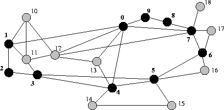
First of all, Figure 2 shows the
topology of the MCI ISP backbone network, which we use throughout the
experiments. In the first set of experiments, all routers (black and grey)
can act as edge routers and core routers as well. This means that the
flows can arrive and leave at every router. In a second set of experiments,
black nodes are edge routers and grey nodes are core routers.
We consider two classes of traffic in this simulation study: one real-time
class and one non-real-time class.
We assume that all flows in the real-time class have a
fixed packet length of 640 bits (RTP, UDP, IP headers and 2 voice frames)
[8], and a flow rate of 32 Kbps.
The end-to-end delay requirement of all flows is fixed at 100ms.3
Thus, the input traffic of each flow is constrained by a leaky bucket with
parameters b = 640 bits and r = 32 kbps.
This kind of QoS requirements is
similar to "Voice-over-IP".
All links in the simulated network have the same capacity of 155 Mbps.
For the sink-tree system we assume that the bandwidth requested for
any path between a pair of ingress and egress nodes remains the same.
In other words, for a node's point of view, it has the same amount of
bandwidth available to every egress node.
In this experiment, the amount of resource for a path between any two
nodes is 1.28 Mbps, which accommodates 40 real-time flows.
For the flat-fixed system, roughly 10.5% of the link capacity is allocated for
the real-time flows.
So, every link can accommodate 510 real-time flows.
The number comes from the fact following.
After the construction of sink-trees,
the total sum of resources allocated
to each link in the sink-tree system divided by the number of total links
gives roughly 16.3 Mbps, which corresponds to 10.5% of 155 Mbps-capacitated
link.
Worst-case End-to-end Delay Table 2 shows the worst-case end-to-end delay (unit : msec.) in each resource sharing strategy4. As can be seen, the no-sharing strategy outperforms flat-fixed, while link-sharing is significantly worse. We interpret this as follows. According to the equations about a (Equations (11) to (14)), the end-to-end delay becomes larger with increasing bandwidth allocated over the link for real-time traffic, while it gets smaller when the link capacity grows. The reason for the smallest value for no-sharing is that Rl,ud is much smaller than Bl,ud. In the case of link-sharing, åu = 1tBl,u may be large enough on some links to produce the worst (largest) value. In flat-fixed systems the resources are distributed evenly over the network. Flat-fixed therefore, produces smaller end-to-end delays than link-sharing. So in terms of performance, sink-tree paradigm, except for link-sharing, provides similar or tighter worst-case end-to-end delays.
| flat- | no- | path- | tree- | link- | |
| item | fixed | sh. | sh. | sh. | sh. |
| worst-case | |||||
| e2e delay | 3.138 | 1.609 | 4.204 | 4.204 | 13.580 |
Maximum Possible Resource Allocation We define the maximum possible resource allocation as the ratio of total resource allocated for the real-time traffic over the total capacity of all links under the condition that the worst-case end-to-end delay reaches up to the worst-case end-to-end delay requirement (Table 3). In the table, UBAC stands for Ütilization Based Admission Control" which was presented in [23]. This approach illustrates the benefit of good path selection: For each possible pair of source and destination nodes, the paths are predefined off-line, and among them, the most promising one (that provides the smallest end-to-end delay) is selected as run-time path. The bandwidth is allocated uniformly over the all links, however. UBAC therefore provides the limit on maximum possible bandwidth allocation for the flat-fixed system with optimal routing. It is important to note here that all proposed network-based endpoint admission control systems, except for the link-sharing strategy, outperform the UBAC system. As can be seen, UBAC gives about 50% performance improvement from the flat-fixed system. However, no-sharing provides 70% improvement from flat-fixed. As expected, as we share more resources, the maximum possible resource allocation gets smaller since the sharing causes loose end-to-end delay.
| flat- | no- | path- | tree- | link- | ||
| item | fixed | UBAC | sh. | sh. | sh. | sh. |
| alloc. | 0.33 | 0.45 | 0.57 | 0.49 | 0.49 | 0.39 |
Admission Probability
We simulate the admission control behavior in the system by simulating
flow requests and establishments at varying rates with a constant average
flow lifetime.
Requests for flow establishment form a Poisson process with rate
l, while flow lifetimes are exponentially distributed
with an average lifetime of 180 seconds for each flow.
Source and destination edge routers are chosen randomly.
In the flat-fixed system, the path is selected using SPF routing.
In the sink-tree system however,
the path is pre-defined in a sink-tree.
Figure 3 shows the admission probabilities for the real-time
class in the five cases
as a function of arrival rates.
In the figure, the legends are that CA1-flat for "Call Admission-probability
with Configuration 1 (black and grey nodes are all edge and core nodes)
in the flat-fixed system", CA1-no for "Call Admission-probability with
Configuration 1 in the no-sharing system" and so on.
As can be seen in Figure 3, the four sink-tree systems
perform better than flat-fixed. Even no-sharing outperforms
flat-fixed. In the case of no-sharing, if we wish to allow
90% chances of flow admission, the performance is
approximately 50% larger than that of flat-fixed.
The importance of this result is that the sink-tree structured resource
management brings a lot of benefit
even when all the bandwidth requirements,
and all link capacity are the same.
The differences between the four resource-sharing strategies in the sink-tree
system are not negligible either.
At 90% chances of flow admission point, link-shared
strategy outperforms no-sharing by about 10%, with a little more
signaling overhead.
If this signaling overhead is light enough to
scale, this improvement is important.
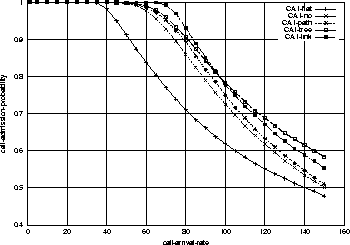
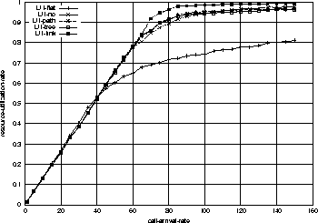
Figure 4 shows the utilization ratios for the five cases.
To be fair, the link utilization is defined by the resource consumed by the
flows in the network divided by the total resources allocated.
So this link utilization is different measure of performance from the
maximum possible resource allocation described earlier in this section.
The former effectively measures the efficiency of allocation, while the
latter provides a limit on the maximum allowable resources
under the worst-case end-to-end delay constraint.
By comparing Figure 4 and Figure 3,
we know that the point of 90% admission probability in no-sharing system
corresponds to 75-calls-per-second.
At this call arrival rate, the flat-fixed system utilizes
resources only around 70%, while no-sharing does around 85%.
In other words, even no-sharing strategy's efficiency is better than that
of the flat-fixed system by about 20% in link resource utilization.
The point is that although the total amount of allocated resources are the
same, the utilization depends on how the resources are allocated.
Therefore the admission probability will be better with an efficient
resource allocation.
The big difference between 50% improvement in admission probability
and 20% improvement in resource utilization comes from the fact that
the number of links requested by a call ranges from 1 to the longest length
of the simple path in the sink tree.
This accommodates more calls requesting the small fragment of resources
rather than the calls requesting longer paths (many number of links).
So the number of calls accepted gets higher.
In overall, the proposed network-based endpoint admission control shows
significant improvement in admission probability over the
flat-fixed system.
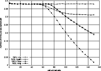
One thing which might look confusing in Figure 3 is that the admission probability of link-sharing goes down below that of tree-sharing at around 80% chances of admission point. We answer this with Figure 5. As can be seen, the number of links per accepted call (average resources per accepted call, which is acronym-ed NOL in the figure) is decreasing in all resource-sharing strategies. Interestingly, the link-sharing's NOL goes over that of tree-sharing's. This must have resulted in the higher admission probabilities for tree-sharing by the same argument (resource fragmentation) mentioned above. In fact, we do not put an emphasis on this because in most real cases, we expect the network will be administered at 90% or more chances of admission points. We consider this as a network configuration-specific result.
Network-configuration Effect on Resource Sharing
To illustrate the effect, we ran the same set of simulations with
Configuration 2, where the core nodes are not the edge nodes any more.
That means only the edge nodes can be the sources or destinations for the flow.
For this particular experiment, the black nodes in Figure 2
are the edge nodes (1,2,3,4,5,6,7,8,9,0),
while the grey nodes are core nodes (10,11,12,13,14,15,16,17,18).
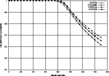
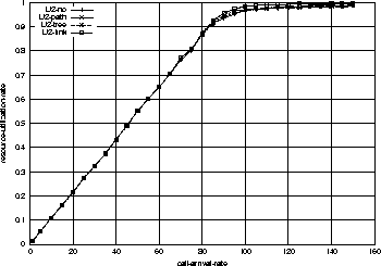
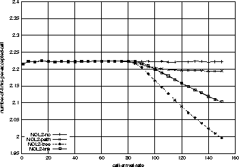
Following three figures 6, 7, and 8
show the admission
probabilities, resource utilization rates, and average resources
per accepted call respectively.
By comparing Figure 3 and Figure 6,
we observe that with Configuration 2, the admission probabilities are
higher and the differences between the resource-sharing strategies are
smaller. For example, the link-sharing has 10% improvement from no-sharing
in Figure 3, while it has only 3% improvement
in Figure 6.
The reason is that because only the edge routers can be
sources and destinations the resources are less fragmented than in
Configuration 1. In other words, in Figure 1, Node 2 and 3 are
not edge nodes anymore, so there is no flow request at these nodes
with Configuration 2. Therefore the benefit of sharing is reduced.
By the same argument, there is only a little difference
in link resource utilization in Figure 7 too.
In overall, it is clear that there is only a little difference in the
admission probabilities and resource utilization among the four
resource-sharing strategies with Configuration 2.
We expect that if we have more pure core routers, the difference
will be much smaller.
Observing these results, we can say that if the number of edge nodes
is relatively smaller compared to the number of total nodes, the resource
sharing does not contribute much for admission probability or resource
utilization.
In this paper, we proposed a network-based endpoint admission control
which: 1) requires the minimum possible signaling overhead, 2) provides
minimum possible latency for a flow set up, zero routing overhead,
high admission probability, high resource utilization, and tight end-to-end
packet delay upper bound.
This is achieved by : 1) having resources structured off-line with sink
tree reflecting the user traffic requirement,
2) at run-time, referring only to the
edge router (the entrance of the network) at which a flow arrives
and which automatically keeps track of the resources available downstream
up to the destination.
This approach is more suitable to the many real-time applications like
Voice-over-IP than the host-based endpoint control.
For evaluation purposes we compared this with the flat-fixed system where
all links have the same capacity and a fixed portion of the link capacity
is allocated for the real-time traffic over the network uniformly
with SPF routing.
Simulation study shows that
the proposed system provides
50% improvement in the tightness of the worst-case end-to-end delay.
Also, in terms of maximum possible resource allocation, it provides
75% improvement, both from the flat-fixed system respectively.
Simulation studies on the admission probabilities show that
no resource-sharing strategy outperforms the flat-fixed system
by up to 50% improvement.
Also, we showed the effect of network configuration on the
resource-sharing by simulations with different network
configurations.
According to the result, there is not much benefit of
resource sharing if the number of edge nodes are smaller compared to
the number of total nodes in the given network.
In the future, we will extend the sink-tree paradigm on a global scale
so that the very large network will be able to support real-time
applications in a scalable fashion.
References
1 Here the RBT indicates that after the dialing, the network checked out there is resource available for the service requested and let the originator know that the network is now alerting the destination. Usually the time required between the two is un-noticeable.
2 From here, the domain is a DS-capable domain; a contiguous set of nodes which operate with a common set of service provisioning policies and per-hop-behavior definitions [12].
3 In these experiments we consider queuing delay only for end-to-end delay deadline. There are many other delay factors, like propagation delay, Codec (Coder and Decoder) delay. More accurate values can be found in [8] and would generate similar results.
4 Here we define that worst-case end-to-end delay the largest possible delay between any pair of source and destination nodes. Because the end-to-end delay analysis used in this paper is interested only in the worst-case delay. The relative order of magnitude in the average end-to-end delay among the five systems might be different from that of worst-case delay.